Dc and ac testing provide an equivalent level of breakdown detection, but the increased accuracy of dc leakage-current detection can reveal marginal insulation systems.
Dielectric withstand testing is used to evaluate wiring insulation. When testing insulation installed in mobile homes, it is important that the insulation be tested at a much greater voltage than normal to ensure that the insulation is not marginal. If voltages are set correctly, dielectric withstand testing using a dc voltage provides the same outcome as using an ac dielectric test. In addition, dc testing offers significant safety and performance improvements over ac testing.
Dielectric testing is a simple, nondestructive method of verifying the adequacy of electrical insulation to withstand transient (surge) events. Transient voltage spikes on power lines are generally the result of nearby lightning strikes, but spikes can also occur for other reasons. In general, such transient spikes have a very short duration--the spike lasts for <20 microseconds.
A dielectric test can verify the performance headroom of the insulation, ensuring that the insulation will not fail because of insulation degradation from aging, moisture, wear due to vibration, or other causes.
The voltage level of the dielectric test is generally adjusted based on the environmental conditions to which the end product will be subjected. A higher dielectric test voltage is used for equipment located where environmental conditions are more severe. Passing this more-severe dielectric strength test when the end product is new indicates that the insulation being stressed has enough headroom to provide adequate protection after the end product has been subjected to environmental degradation.
Test Method. In dielectric testing, a high voltage (typically ≥1000 V) is applied between two conductors that are supposed to be electrically insulated from each other. If the two conductors (e.g., an insulated live wire and a metal enclosure) are completely isolated from one another, then the application of a large voltage difference between the two conductors would not allow current to flow between the conductors. In this case, the insulation is said to withstand the application of a large voltage potential between the two conductors, hence the term dielectric withstand test.
In general, two dielectric test results indicate insulation failure. The first is excessive current flow during the test due to low insulation resistance of the insulating material separating the two conductors. The second is an abrupt dielectric breakdown due to electrical arcing or discharge, either through the insulation material, over the surface of the insulation material, or through the air.
Test Voltage. If the test voltage is too low, the insulation material will not be adequately stressed during the test, allowing inadequate insulation to pass the test. On the other hand, if the test voltage is too high, the test could cause permanent damage to an insulation material that is otherwise adequate for the application. A general rule of thumb used for testing mains wiring that operates at voltages of 120–240 V ac is 1000 V plus two times the operating voltage. Using this rule, 120-V wiring would be tested using a voltage of 1000 V + (2 x 120 V) = 1240 V ac.
Test Duration. To adequately stress the insulation, the test voltage is generally applied for 1 minute. However, many standards allow the test duration to be reduced to 1 second for production line testing to accommodate the large volume. For reduced-duration testing, standards often require the test voltage to be increased by 20% to ensure that 1 second is sufficient to test the insulation adequately.
Ac versus Dc
Test Waveform. The nominal line voltage in the United States is 120 V ac. The waveform of the voltage is sinusoidal, and the frequency of that voltage is 60 Hz (cycles per second). The voltage of 120 V refers to the root-mean-square (rms) value of the ac voltage. The rms value of an ac voltage provides a mathematical equivalent to the heating value of a dc voltage. In other words, an ac voltage of 120 V rms applied to a resistor (or a nichrome wire heater) would generate the same heat output as when a dc voltage of 120 V (e.g., from a battery) is used.
The instantaneous voltage of 120 V ac at 60 Hz varies with time. In one cycle, which repeats 60 times per second, the voltage will start at 0 V, increase to a peak of about 170 V, drop down to 0 V again, continue to drop to a negative peak of –170 V, and then increase again to 0 V (see Figure 1). Taking the simple average of the voltage over one cycle results in a value of 0 V. Calculating the rms value results in a measurement of 120 V. By definition, the peak of a sinusoidal waveform is the rms value times the square root of 2 (i.e., Vpeak = Vrms x 1.414). Figure 2 shows an ac waveform with an rms voltage of approximately 1000 V. Note that the positive and negative peaks of the waveform exceed +1400 V and –1400 V, respectively.
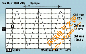
Figure 1. A 120-V ac rms waveform at 60 Hz.
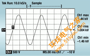
Figure 2. An ac waveform with an rms voltage
of about 1000 V.
Test Voltages. The intent of the dielectric test is to stress the insulation for a short period of time and check that it does not fail. Testing using a 60-Hz ac voltage is done only as a matter of convenience--a transformer with a high-voltage secondary winding (e.g., a neon-sign transformer) can be used to generate the high voltage needed to perform the dielectric test. A 60-Hz ac test voltage cannot simulate real-world events any better than a dc test voltage can. Even high-voltage transients (surges) that appear on the 120-V ac mains are not ac; they are momentary voltage spikes with a typical duration that is measured in microseconds (millionths of a second) or milli-seconds (thousandths of a second).
Any decisions regarding the use of ac versus dc voltage for testing must consider the intent of the test, which is to stress the insulation being tested. The higher the voltage, the more stress is applied to the insulation. When an ac test voltage is used, the highest amount of stress is applied to the insulation at the moments when the test voltage is at a positive or negative peak. At other points of the sinusoidal ac waveform, the electrical stress is lower.
An ac test voltage of 1000 V rms will have voltage peaks of 1414 V. Therefore, if a dc test voltage is used, the test voltage must be increased to 1414 V dc to produce the same level of stress to the insulation as would 1000 V ac rms. The dc test voltage is shown in Figure 3. Note that the peak test voltages in both Figures 2 and 3 are the same.
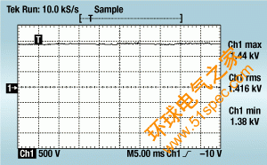
Figure 3. A 1414-V dc test voltage.
The difference in test voltage for dc compared with ac is supported by national testing and standards writing organizations such as Underwriters Laboratories, Factory Mutual Corp., the Institute of Electrical and Electronic Engineers, and the American National Standards Institute, as well as international organizations such as the International Electrotechnical Commission.
Dielectric Breakdown evaluation. Because the electrical stress on the insulation is highest at the peak of the ac waveform, dielectric breakdown occurs at the peak of an ac test voltage. Figure 4 is an oscilloscope display of an ac-voltage dielectric breakdown. Note that the waveform is smooth as the voltage increases to the peaks, then abruptly breaks down at the peak voltage. Figure 5 shows the occurrence of a similar dc-voltage breakdown.

Figure 4. An ac-voltage dielectric breakdown.

Figure 5. A dc-voltage dielectric breakdown.
It is important to note how abruptly a dielectric breakdown occurs. In Figure 6, the ac breakdown in Figure 4 has been expanded 50,000 times--the time base on the oscilloscope has been changed from 5 milliseconds to 100 nanoseconds to zoom in on the breakdown event. The time that it takes for the voltage to drop from the peak value to 0 V is 10 nanoseconds, approximately a million times faster than the period of the 60-Hz ac test voltage waveform.
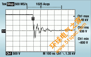
Figure 6. A zoomed-in ac breakdown.
Because the breakdown occurs so quickly, and because it occurs at the peak voltage of the ac waveform, the ac and dc voltages appear exactly the same to the breakdown; that is, it appears as a peak voltage of very long duration. In other words, the peak voltage of the ac waveform lasts much longer than the breakdown itself.
Figure 7 illustrates a breakdown similar to that shown in Figure 6, except the test was conducted using a dc voltage of 1.414 times the rms value of the ac waveform. A comparison of Figures 6 and 7 shows that the behavior of a breakdown under both ac and dc conditions, respectively, is identical.
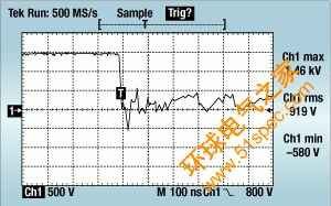
Figure 7. A zoomed-in dc breakdown.
Advantages and Disadvantages. Historically, dc test voltages are more difficult to generate, resulting in the need for more-costly, complicated test equipment. This disadvantage is offset by the performance and safety advantages gained from using dc test voltages. To explain these advantages, some additional background information is needed.
An electric charge develops whenever a voltage difference is applied between two conductors that are separated by an insulator. The amount of charge created is proportional to the voltage applied and to the capacitance between the two conductors. If charge is represented by Q, voltage by V, and capacitance by C, then the mathematical relationship between these three quantities can be represented as Q = C x V.
In practical applications, capacitance can exist due to discrete capacitors, but capacitance can also be created inadvertently when two conductors with a voltage difference are placed close together. Examples of this type of capacitance can be found in electric motors, transformers, multiconductor electrical wiring, and single-conductor wiring that is routed near metal. If the voltage is varied, the charge varies. If the voltage swings in both positive and negative directions, then the charge will do the same.
A second fundamental concept is that electric current will flow through a capacitor whenever the voltage changes. This is because as the voltage is increased across a capacitor, the amount of charge increases. Electric current is simply a measurement of how much the charge changes over a period of time. Current is often represented by I, which is measured in amperes, or amps. The amount of charge Q is measured in coulombs. One amp of current is defined as a charge flow of 1 coulomb per second.
Combining the concept of capacitance with that of current yields the following. A changing voltage generates a changing charge. By definition, this changing charge is the flow of electric current. Therefore, a changing voltage causes current to flow between two conductors. Because of the capacitance between the two conductors, this current can flow between them even when they are physically insulated from each other. The greater the capacitance is between the conductors, the greater the current flow will be.
When performing dielectric tests using an ac test voltage, an electric current will flow between the two points being tested (due to the capacitance between the two conductors). This current does not represent a failing test result from having a low insulation resistance. Therefore, an ac dielectric tester must compensate for this allowable flow of current. The most common method to accomplish this is to allow the tester to detect a significant amount of current (typically ≥20 mA) without indicating an excess current failure. If multiple products are tested with the same dielectric tester, this current-limit set point may need to be adjusted even higher to accommodate the equipment with the greatest capacitance between the conductors being tested. In other words, the dielectric tester must be desensitized so that it will ignore current levels <20 mA (for example). This situation creates two very dangerous problems.
The desensitized ac dielectric tester cannot tell the difference between 5 and 15 mA. Consider what happens if the circuit under test has capacitance between the conductors that causes 5 mA to flow in normal conditions during the test. A device under test (DUT) with faulty insulation that allows 300% of the normal amount of current to flow (15 mA) would still be considered an acceptable test result by the desensitized ac dielectric tester.
The desensitized ac dielectric tester can supply a lethal amount of current to the human body and still not shut down due to excess current. For example, if the DUT is sinking 5 mA, and the test operator comes in contact with the test voltage such that 10 mA flows through the operator, a total of 15 mA would be sourced by the tester. Because 15 mA is less than the 20 mA current-limit set point, the tester does not shut down, allowing the operator to be seriously injured or killed.
When performing dielectric tests with a dc test voltage, electric current flows only while the voltage is being ramped up from 0 V to the final test voltage. In this case, the current flow is very small because the voltage is typically ramped up over a period of 1–2 seconds, compared with an ac test voltage that goes from a positive peak to a negative peak and back again 60 times per second (remember that the current flow is proportional to the change in voltage over time). In fact, a dc test voltage that is ramped up over a period of 2 seconds causes only 1/120 (<1%) of an ac test voltage's current flow. As soon as the dc voltage reaches the final test level, the current essentially stops altogether. In most cases, the amount of current that flows during a dc dielectric test is negligible, regardless of the amount of capacitance that exists in the DUT.
When compared with an ac dielectric test, dc testing offers many advantages. The maximum allowable test current can be set to a much lower level (1 mA is typical). The dc tester shuts down when more than 1 mA of current flows during the test. This highly sensitive test allows the operator to identify marginal constructions that would have been overlooked by an ac tester.
The lower test-current levels are significantly safer for the operator. At 1 mA, the current is enough to shock the operator, but the test current would be automatically shut off when the current flow exceeds 1 mA.
Conclusion
The question of whether to use ac or dc dielectric testing has nothing to do with the fact that the insulation being tested is normally subjected to 120 V ac. A dielectric breakdown occurs in nanoseconds. All of these events happen so quickly that a varying 60-Hz ac voltage effectively becomes an unchanging dc voltage. If the peak voltages of an ac and dc dielectric withstand test are the same, then both types of testing can verify the suitability of insulation used between conductors. For the peak voltages to be equal, the dc voltage used in a dielectric withstand test must be 1.414 times the ac rms voltage used.
Dc testing offers significant advantages over ac testing. Dc and ac testing provide an equivalent level of breakdown detection due to total insulation failure. However, the heightened accuracy of dc leakage-current detection allows marginal insulation systems to be detected. Dc dielectric testing is superior for ensuring operator safety. Neglecting to consider dc testing as an alternative to ac testing potentially jeopardizes both the test operator (with shock hazards during testing) and the consumer (with marginal insulation).


