Martin Staebler co-authored this technical article.
The use of electric motors in electronic systems has become pervasive. Innovations in motor size, control and cost efficiency have enabled designers to add electric motors to systems, thus creating new features and extending the functionality of end products.
With the dramatic increase in the number of electric motors, concerns over power efficiency have driven system designers to use higher-voltage motors and increase the effective power efficiency of their designs. The use of higher-voltage motors in systems has also presented designers with challenges in ensuring user safety.
To address these design challenges, system engineers have leveraged solutions such as optocouplers and digital isolator devices, which help isolate the higher-voltage side of the main data path from the lower-voltage portion. Isolation helps ensure that any stray signals or malfunctions do not accidentally power on the motor or cause unexpected motor-drive system behavior that could impact safety or damage lower-voltage circuitry. Although isolating the main data path is critical to higher-voltage-system designs, often it is the lower-level control signals – those that are not part of the main data path – that present challenges when implementing a safe solution.
There are standards to guide designers who need to implement safer higher-voltage motor-drive solutions. One example is International Electrotechnical Commission (IEC) 61800-5-2, which provides guidelines about the functional safety requirements of adjustable-speed electrical power-drive systems. Essentially, IEC 61800-5-2 helps define implementation approaches so that control architectures for motor-drive systems do not enter a state where the motor could turn on inadvertently or result in higher voltages finding a path to the user.
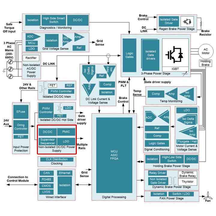
One of the new areas that this standard addresses, which is directly related to the challenges of implementing safe high-voltage motor-drive solutions, is safe torque off (STO). STO as described in IEC 61800-5-2 is an implementation approach that prevents force-producing power from being provided to the motor. As shown in Figure 1, a servo drive power-stage module has many interconnect points outside of the main data path to consider when applying STO in a motor-control system design.

Figure 1: Insulated-gate bipolar transistor-based servo drive power-stage reference diagram
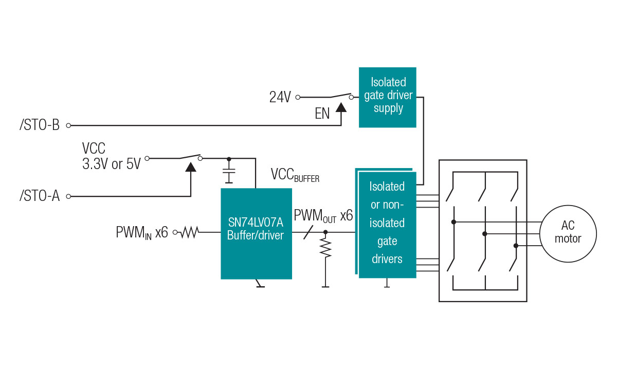
Motor-drive system designers can leverage simple logic devices already present in many designs to help implement STO in their systems. Many logic devices offered by Texas Instruments have Ioff circuitry, which helps prevent damaging current backflow through the device when powered down. Because logic devices with Ioff have isolation during power off, it is possible to use the Ioff feature in simple logic and level-shifting devices to implement STO control signals in motor-drive applications. Figure 2 shows an example STO implementation, where an emergency off switch triggers STO.
 Figure 2: A simplified STO implementation example (isolated 24-V input receiver for /STO-A and /STO-B not shown)
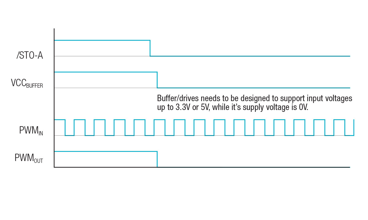
In Figure 2, the active low /STO-A signal removes power from the pulse-width modulation (PWM) buffer and all gate-drive PWM inputs are driven low. The gate driver opens all of the power switches, which removes torque from the motor, as depicted in Figure 3’s timing diagram.
 Figure 3: Timing diagram for an /STO-A emergency off-switch implementation
An active-low /STO-B signal would turn off the isolated power supply, which supplies each of the six gate drivers. In the example for /STO-A, the SN74LV07A Ioff-capable hex buffer plays a key role in ensuring that the motor remains off. An alternative to a six-channel hex buffer is to use six single buffers/drivers such as the SN74LVC1G07.
For a deeper technical look at Ioff functionality, read the technical article, “Logic gates and switches with Ioff – empowering you to power down.” TI has a large portfolio of Ioff-capable logic devices including buffers, gates, switches and level-translation devices that can help you meet almost any motor-drive control application need. For more information, see TI’s logic portfolio and motor-drive applications.
Additional resource:


