Everyone agrees that seeing clearly on the road is essential while driving a car. This truth becomes even more critical when implementing technologies such as autonomous driving. The “eyes” of an autonomous vehicle are called light detection and ranging (lidar) technology, which provides precise images of what surrounds the vehicle. Lidar systems use a light source and sensor to detect objects.
The field of view (FOV) of a lidar system is crucial to the autonomous driving decision algorithm because it defines the width of the lidar’s captured images. There are many ways to increase the FOV: one way is to leverage mechanical scanning, using a motor to help achieve a 360-degree FOV. Brushless DC (BLDC) motors have become popular for this purpose because of their efficiency and low noise.
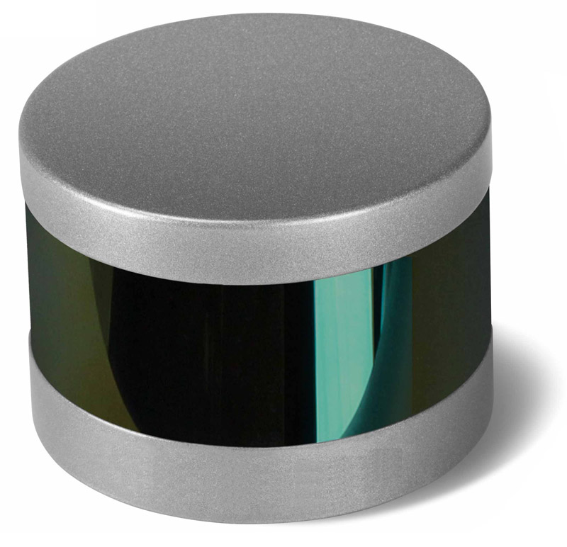
Figure 1 shows a lidar module, while Figure 2 shows an autonomous vehicle with lidar.

Figure 1: Lidar module

Figure 2: An autonomous vehicle equipped with lidar
Autonomous driving with mechanically scanning lidar
A typical lidar module includes a light source and sensor and can achieve a 120-degree FOV. Unfortunately, 120 degrees of vision is insufficient in an autonomous driving environment. To achieve a full 360-degree FOV, a mechanically scanning lidar system comprising a light source and a sensor on a rotating platform feeds information around the vehicle into the car’s advanced driver assistance system. The rotating platform spins at a speed that enables the light source and sensor to traverse 360 degrees, with accurate feedback of image positions. Given the platform’s low weight, it’s possible to use a motor of around 40 W.
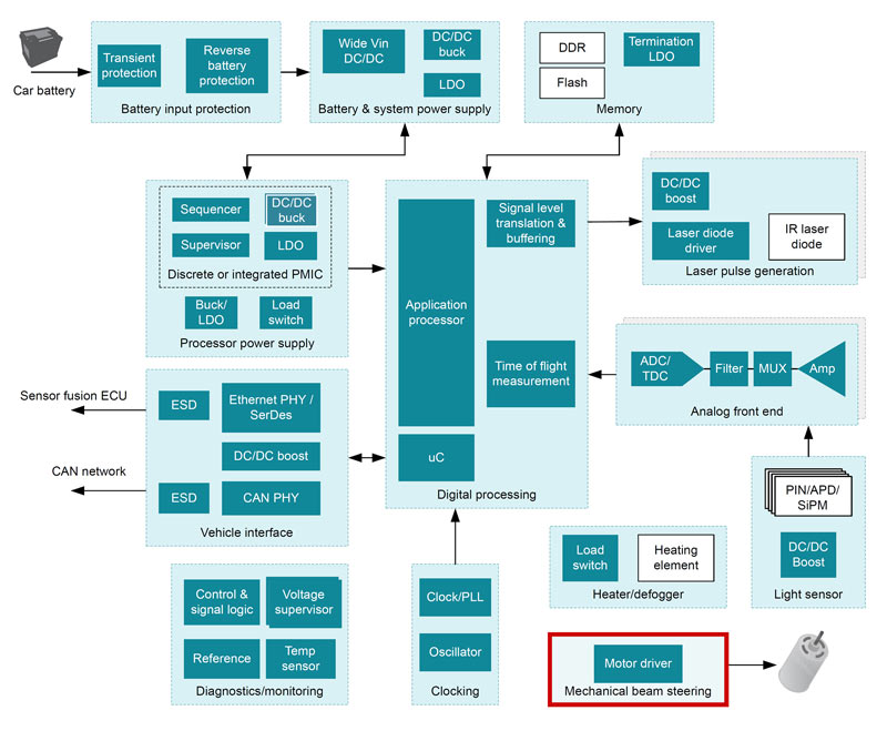
BLDC motors are a good fit for these rotating platforms, and it’s possible to implement commutation of the BLDC motor using Hall-effect sensors. Figure 3 shows a block diagram of mechanically scanning lidar.

Figure 3: Mechanically scanning lidar block diagram
How to drive a BLDC motor
There are a few ways to drive a BLDC motor for around 40 W of power. You could use a microcontroller (MCU) with a trapezoidal commutation algorithm together with an integrated three-phase BLDC gate driver and external metal-oxide semiconductor field-effect transistors (MOSFETs). If the application calls for a limited board size and low motor power, consider an integrated MOSFET three-phase gate driver such as the DRV8316, along with an MCU incorporating the commutation algorithm and three Hall-effect sensors for position feedback. The DRV8316 integrates 95-m-ohm combined high- and low-side on-state resistance (RDS(on)) MOSFETs, and provides comprehensive fault coverages for diagnostic purposes.
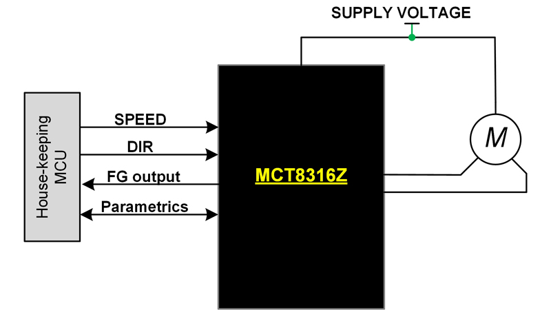
There are also control algorithm-integrated motor drivers available to drive a BLDC motor such as the MCT8316Z, which eliminates the need to develop motor-control software by integrating sensored trapezoidal control. The MCT8316Z has integrated MOSFETs with combined high- and low-side RDS(on), which is the same as the DRV8316 at 95 m-ohm. An external housekeeping MCU can communicate with the MCT8316Z to set configuration parameters and provide simple spinning commands such as speed and direction.
The MCT8316Z has an integrated DC/DC buck converter that can supply current for the housekeeping MCU or other circuits on the board, a configuration that can help save board space for the mechanically scanning lidar motor driver. Both the DRV8316 and MCT8316Z operate from 4.5 V to 35 V, making these drivers fit for 12-V battery applications in vehicles. With 8-A peak motor winding current support, these drivers can push up to 70 W of motor power at a 24-V power supply that can sufficiently drive the rotating platform of the lidar system.
The MCT8316Z is highly configurable through its Serial Peripheral Interface, although system designers may choose to use the hardware interface option to configure the most frequently used settings without SPI. Detailed fault diagnostics are available through internal driver registers that can be read through SPI which helps diagnosing in case of the motor in the rotating platform having issues. Figure 4 shows a simplified MCT8316Z usage example.

Figure 4: MCT8316Z motor-control example
Autonomous vehicles with mechanically scanning lidar represent an exciting development in the automotive world. The convenience brought by autonomous vehicles improves driving and passenger experiences. I long for owning such a car to go on interstate road trips.
Additional resource


