The first three installments of this technical article series focused on the benefits of designing with low-power amplifiers and how to maximize their efficiency. Unfortunately, low-power amplifiers also come with their share of trade-offs. In this fourth installment, I will consider one of the most common challenges with low-power amplifier designs – instability – and how to resolve this issue with a simple technique.
Most operational amplifier (op amp) applications use amplifiers in a negative feedback loop, where the output signal (OUT) connected to the inverting input (IN–). Negative feedback is necessary to ensure the output voltage adjusts to keep the inputs at the same voltage level. This adjustment prevents the open-loop gain of the op amp, which is typically 1 V/MV or 120 dB, from railing the output of the amplifier to one of the supply voltages. Thus, negative feedback helps keep the output of the amplifier stable and predictable.
Unfortunately, simply feeding OUT back to IN– is not sufficient for ensuring stable, negative feedback. If the output signal is delayed on its way back to IN–, the voltages on the input pins will not match. The output voltage will then overcorrect and overshoot its final value in an attempt to fix the problem. The consequence of this effect is a long, output settling time. If the delay becomes long enough, the feedback signal will have enough phase delay such that it will look like positive feedback instead of negative feedback. The result will be unwanted oscillations, as shown in Figure 1.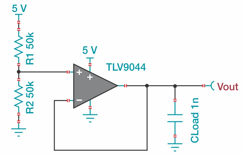
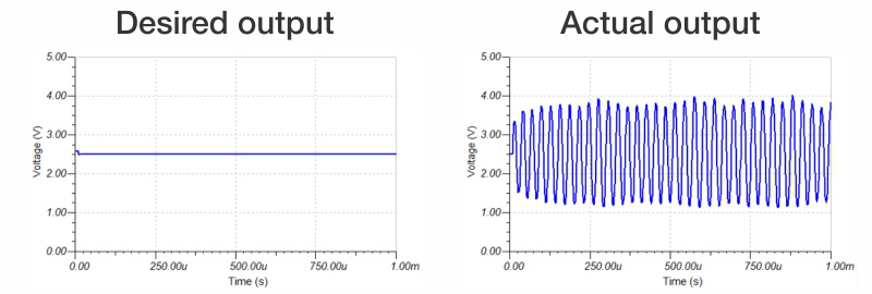
Figure 1: Unexpected op amp instability
Large resistor-capacitor (RC) time constants in the feedback network are the cause of such delays. A combination of the op amp’s open-loop output impedance (RO) and the amplifier’s load capacitance (CLoad), or a combination of a large feedback resistance (RF and RG) with the op amp’s input capacitance (CCM and CDiff), form RC time constants. Figure 2 shows an example of these components in an op amp circuit. Note that some elements are internal to the op amp and others are external. The larger the RC time constant, the longer the delay.
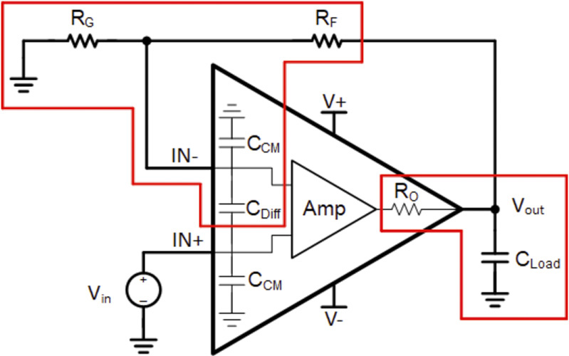
Figure 2: Common sources of op amp instability
Circuits that use low-power op amps are particularly vulnerable to stability issues because the low-power op amps themselves have a large open-loop output impedance. For the low-power op amps in Table 1, as the quiescent current (IQ) and gain bandwidth product (GBW) decrease, the open-loop output impedance of the amplifiers increases, making low-power devices unstable even with lighter capacitive loads. Additionally, circuits with low-power op amps are likely to use large feedback resistors to save power, further worsening stability.
|
Typical specifications
|
TLV9062
|
TLV9002
|
TLV9042
|
TLV8802
|
|
Supply voltage (VS)
|
1.8 V-5.5 V
|
1.8 V-5.5 V
|
1.2 V-5.5 V
|
1.7 V-5.5 V
|
|
Bandwidth (GBW)
|
10 MHz
|
1 MHz
|
350 kHz
|
6 kHz
|
|
Typical IQ per channel at 25°C
|
538 μA
|
60 μA
|
10 μA
|
320 nA
|
|
Open-loop output impedance at 10 kHz
|
100 ?
|
1.1k?
|
7.5k?
|
190k?
|
Table 1: Comparing low-power op amps
Techniques for stabilization
The most common approach to stabilization is the isolation resistor (Riso) method, which is used for amplifiers with capacitive loads. This stability technique only requires the addition of a single resistor at the op amp’s output after the feedback loop, and this resistor generally does not have to be too precise. Although isolation resistors may be large and contribute to output errors caused by voltage drops, most low-power circuits have low-current outputs. So, the isolation resistor’s main drawback is often not a significant issue for low-power op amps.
So how does the Riso method work? A capacitive load on the output interacts with the open-loop output impedance of the amplifier to create an RC time constant. This RC time constant introduces a significant delay into the feedback path. An excessive delay can effectively turn the negative feedback loop into a positive feedback loop. Placing an appropriately sized Riso component (as shown in Figure 3) counteracts the effect of the RC time constant and reduces the feedback delay. The result is a more stable circuit. The TI Precision Labs op amps video series offers a more mathematically rigorous explanation of this effect.
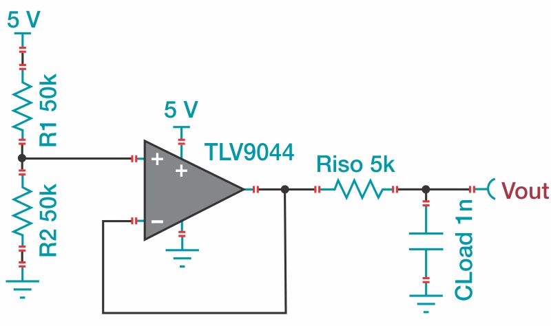
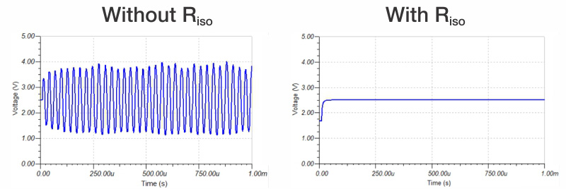
Figure 3: Improved op amp stability
Although the Riso method is an effective technique, it is not appropriate for every application. For example, the interaction of a large feedback resistance with the input capacitance of an amplifier can sometimes cause instability. This interaction is more common in low-power amplifier circuits with gain; think of it as another delay in the feedback network. To counter this effect, you can choose to use a feedback capacitor (CComp) that’s similar in size to the input capacitance of the amplifier (represented by the sum of the common-mode input capacitance [CCM] and the differential-mode input capacitance [CDiff] from the data sheet), thus canceling the time constant formed by the input capacitance and feedback resistance.
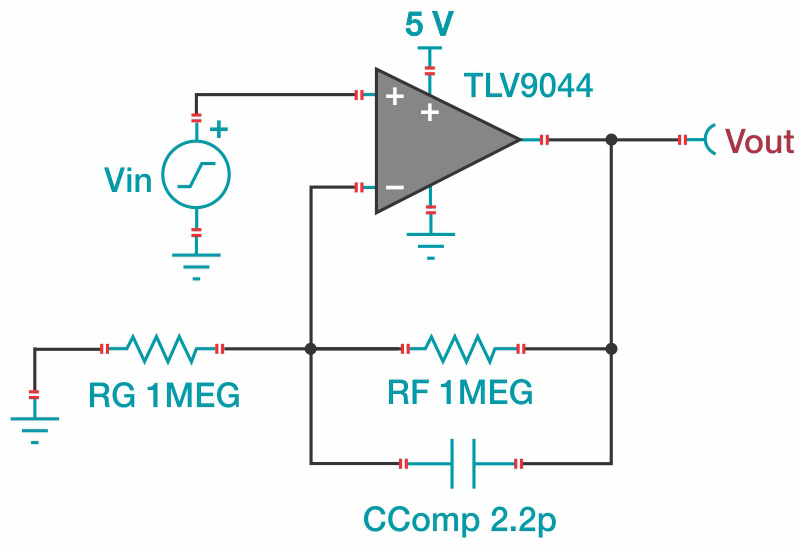
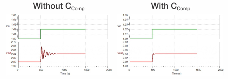
Figure 4: 20-mV step input with and without CComp
As a practical consideration, I recommend including printed circuit board (PCB) footprints for Riso and CComp along with corresponding test points on your circuit board near your low-power op amp circuit. Doing so enables quick fixes to stability issues with the addition of a component, and is much easier and less costly than redesigning the PCB. When not needed, you can replace Riso with a 0-? resistor and leave CComp unpopulated.
Conclusion
Low-power op amps are important components in power-constrained applications. Unfortunately, these devices come with stability challenges. Using the techniques described above, these difficulties can be alleviated and you can enjoy the power savings of a robust, low-power op amp circuit design. The next and final installment will examine noise in low-power amplifiers.


